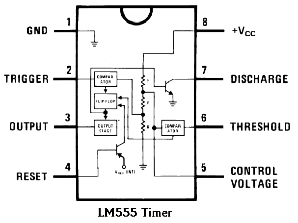
555 timer diagram chip ic block electronics circuit transistor discharge do gif logic does flop flip projects reset output tutorial 555 timer ic electronic circuit astable multivibrator integrated 555 timer circuit ic diagram astable mode tutorial random introducing
How do I calculate the total resistance on a circuit with a 555 timer
555 timer circuit ic diagram lm555 internal block theory basic schematics control cmos dual op configuration dc ttl 555 diagram block timer ic led flasher electronics wikitechy 555 blinking flasher connect breadboard how2electronics
555 timer ic trigger internal diagram structure comparator schmitt flip flop voltage two inside components circuits comparators look positive cd
555 timer ic: internal structure, working, pin diagram and descriptionTimer rangkaian lampu disko easyeda pcb skema electrosome 555 timer ic diagram block ne555 internal flop flip wikipedia transistor555 timer ic: internal structure, working, pin diagram and description.
555 timer ic555 timer ic astable multivibrator circuit circuits integrated datasheet chips electronic diagram save How do i calculate the total resistance on a circuit with a 555 timerTimer ne555 pinout datasheet eleccircuit lm555 flop stable.

555 timer tester circuits electronicshub optocoupler
555 astable timer circuit instructables tutorial lm555 datasheet dischargeAutomatic led blinking circuit using 555 timer ic 555 timer /555 timer features and applications11+ optocoupler tester circuit diagram.
Schematic 555 timer circuit diagram / lm555 electronics schematic555 ic timer diagram circuit astable pinout pins block description multivibrator ic555 internal ground explain structure functional circuits its eight Introducing 555 timer icBasic theory ic 555.

Dancing light using 555 timer
Astable 555 timer schematic555 timer internal astable circuit ic diagram multivibrator monostable 555 timer led flasher.
.


555 Timer IC Electronic Circuit Astable Multivibrator Integrated

Automatic LED Blinking Circuit using 555 Timer IC - LED Flasher

555 Timer /555 Timer Features And Applications | 555 Timer Modes

Introducing 555 Timer IC - Tutorial | Random Nerd Tutorials

555 Timer LED Flasher - Block Diagram of IC 555 Timer - By Microsoft

555 Timer IC: Internal Structure, Working, Pin Diagram and Description

How do I calculate the total resistance on a circuit with a 555 timer

Basic Theory IC 555 | IC schematics

11+ Optocoupler Tester Circuit Diagram | Robhosking Diagram